Tuesday, November 13, 2007

Alright. On a scale of one to ten, what would you consider the likelihood you might be assassinated?

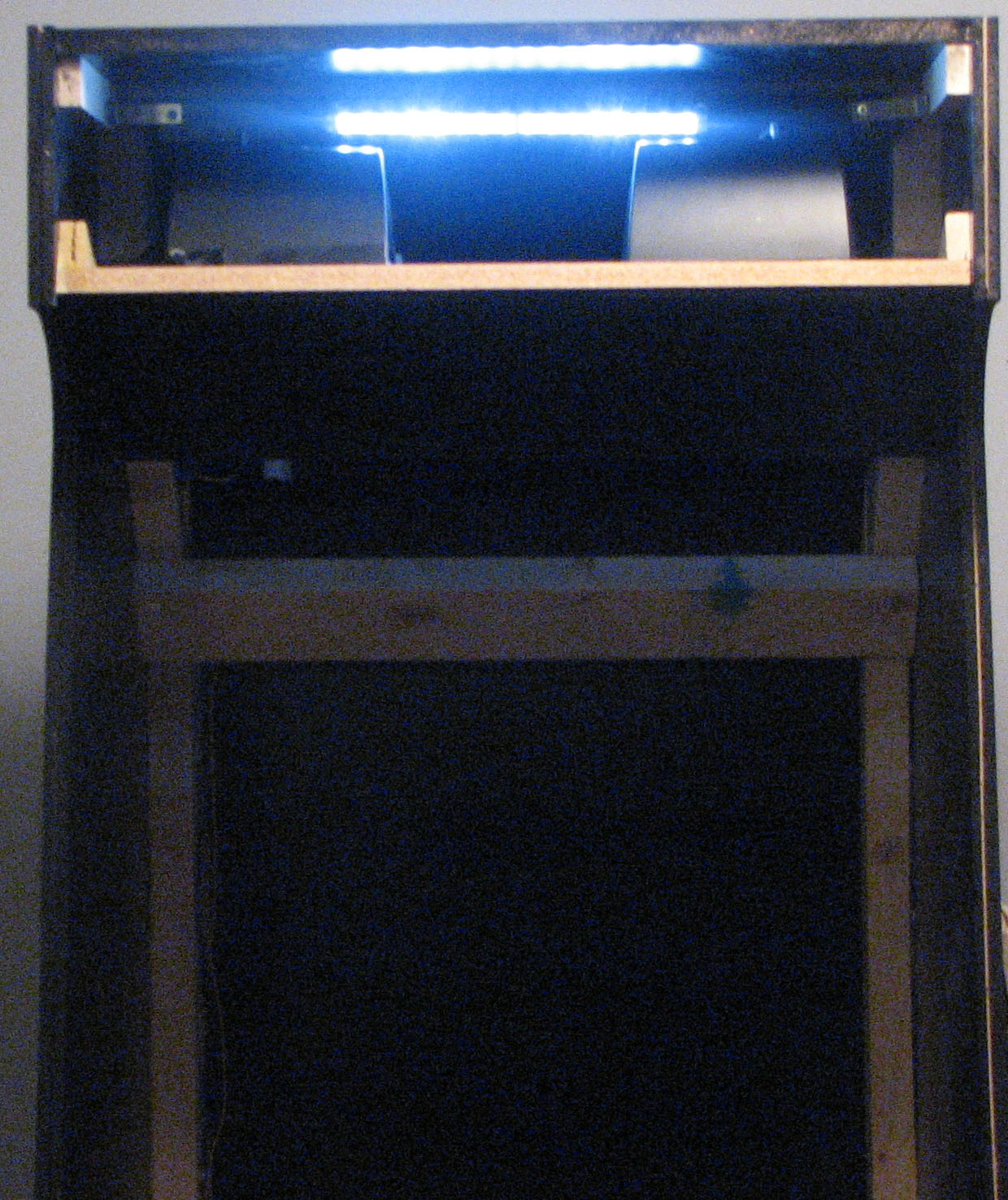
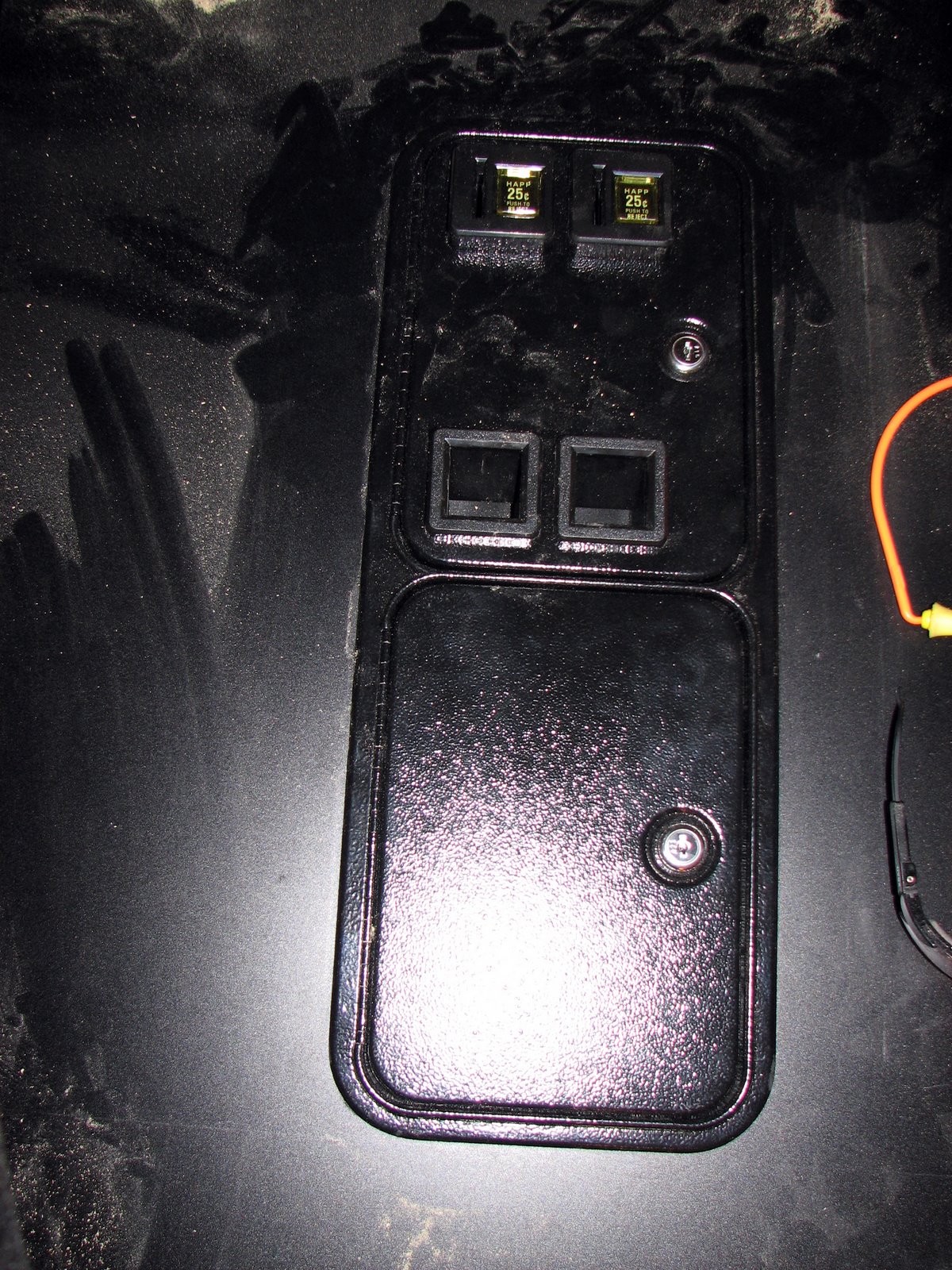
Managed to be productive on the cabinet. Installed the bezel, as the only things remaining now are the tinted glass, and coin door.

Bad news on the control panel artwork, unfortunately the person I had in mind won't be able to do it for me. That means I'm left designing the artwork myself which means this could end in disaster.


I was at a bit of a loss of how to attach the bezel, as it sticks out slightly from the monitor and doesn't sit flush to any mounting surface. I settled on a 2x4 block cut length wise, and some industrial strength velcro.


The difference between regular velcro and industrial strength is night and day. I'd feel completely comfortable hanging 10 or 15 lbs off of this without it pulling loose.


Needless to say, pulling the bezel off the blocks and aligning it squarely was a challenging task.


The finished product neatly hides the mounting material behind it, and when the tinted glass is installed you won't be able to see the bezel at all. Some original arcade cabinets had artwork on the bezel as well, but given my difficulty with the marquee, side art and control panel overlay I'm not going to push my luck.


Once it's assembled, this should give you a pretty good sense of what it will look like. The t-molding on the control panel will go on after the overlay is applied giving it a nice finished look.


Monday, November 5, 2007

It's getting exciting now, 2 and 1/2. Think of everything we've accomplished, man.

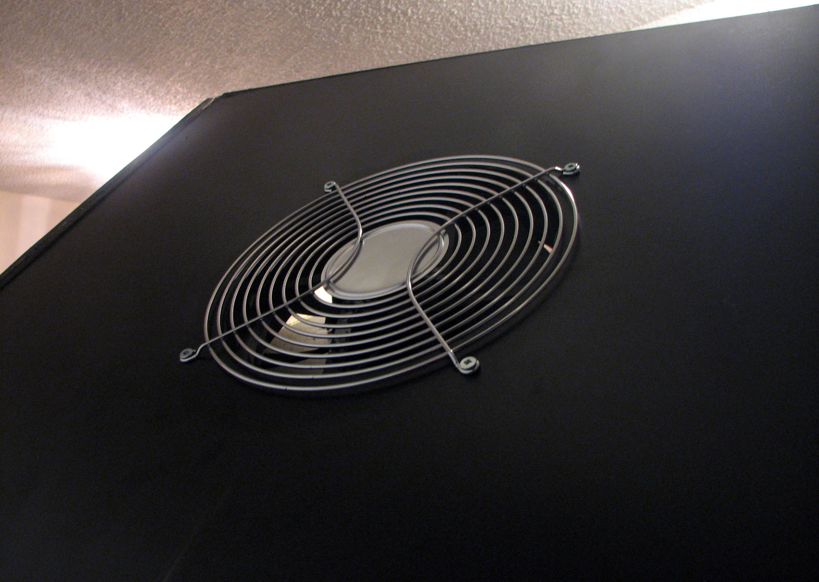
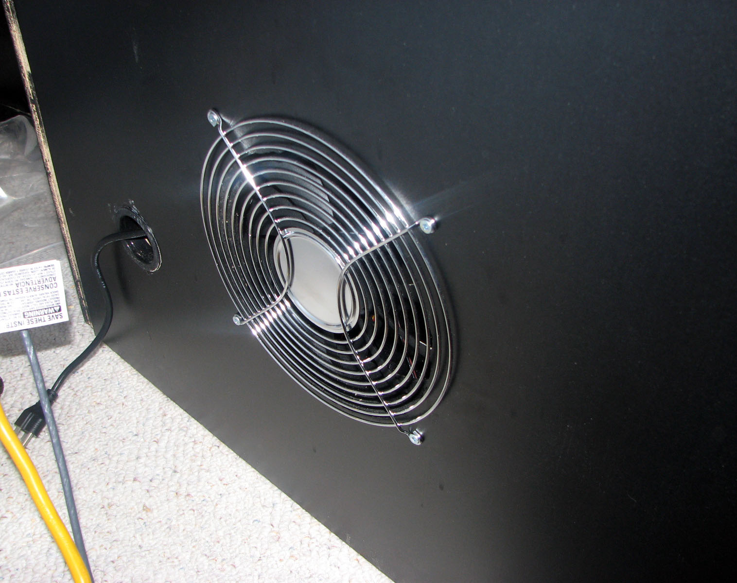
Well it's been some time since my last update, and I've managed to do quite a bit of work. The first thing I did was to mount the fan grills. I ended up going with 254mm fan guards and they turned out fantastic.


After that was done I turned my attention to getting the marquee light mounted. I didn't think I'd have an opportunity to easily mount it and do the wiring if the monitor was in place.


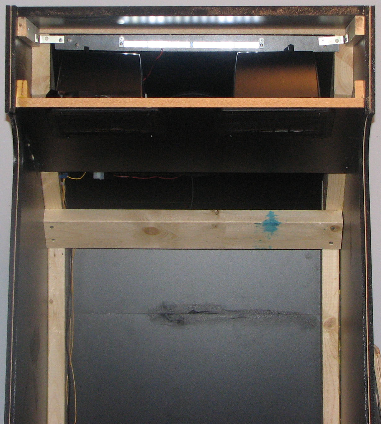
Then my attention was turned to mounting the monitor. I used 2 1/2 inch bolts through some 2x4 spruce cut to 26 inches. The bottom part of the monitor was screwed into some blocks that were angled to get the correct position of the monitor.


The spruce was then attached to the cabinet with corner brackets.


Then on Saturday and Sunday I focused on getting the T molding installed. As we used a 3/32 inch slot cutting bit, I ended up using silicone to hold the T molding in place. J suggested this, and although it was a bit more work the results turned out well.


Then after the T molding was in place I installed the 4 corner protectors. The results are nice, and it adds a completed touch.


Now I'm waiting on the control panel artwork to be finalized, and I have a friend printing off the control panel template on a wide format printer so I can ensure all the holes line up.

Monday, October 22, 2007

How are you going to run the universe if you can't answer a few unsolvable problems?

Well I've managed to get quite a bit done since my last update. I mounted the speaker shelving, the front door, wired the speakers, wired the back and top fans, and wired the marquee light.

Tonight I'll likely be mounting the marquee light and the coin door, and spending the next few days wiring the coin door and control panel.

Once I get the monitor mounted I can start working through any play bugs, and polish up the software side of things. At that point I can also order up the smoked glass for the cabinet. Those are all minor details, however.

This weekend was very productive. J and I managed to get the control panel fabrication completed. On Saturday we spent the first part of the day looking at my layout, and then laying it out again to make it as consistent and clean as possible.

Once grid lines had been set out, finding the spots I needed to drill for the joystick holes and buttons was quite quick. We had a bit of a dilemma when it came to top mounting the joysticks, but in the end we solved it by using carriage bolts, and I'll simply remove the cherry switches from the bottom of the joystick prior to mounting. Otherwise we would have had to make the hole quite a bit larger to accommodate the switches sticking out. Doing so would have weakened our mounting points.

Sunday was largely spent finishing and routing. Several hours of routing the trackballs and joysticks left both of us covered in dust and exhausted. We had a small incident while routing the T-molding groove, but nothing that some silicon won't take care of.


Although it's a bit faint, you can see the angled lines we drew to lay out the joystick, button and trackball mounting points.
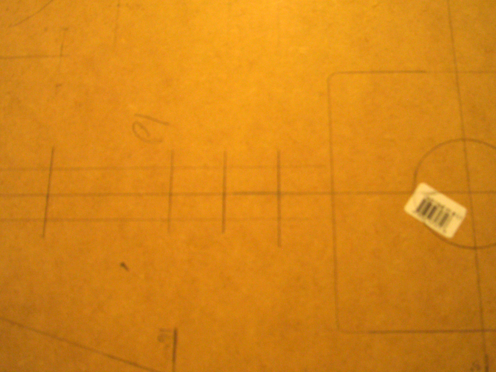
Each of the intersections of the grid lines represent a point I need to drill for buttons. 1.5" spacing between the buttons and 3.5" from the center of the joystick hole to the center of the first button.
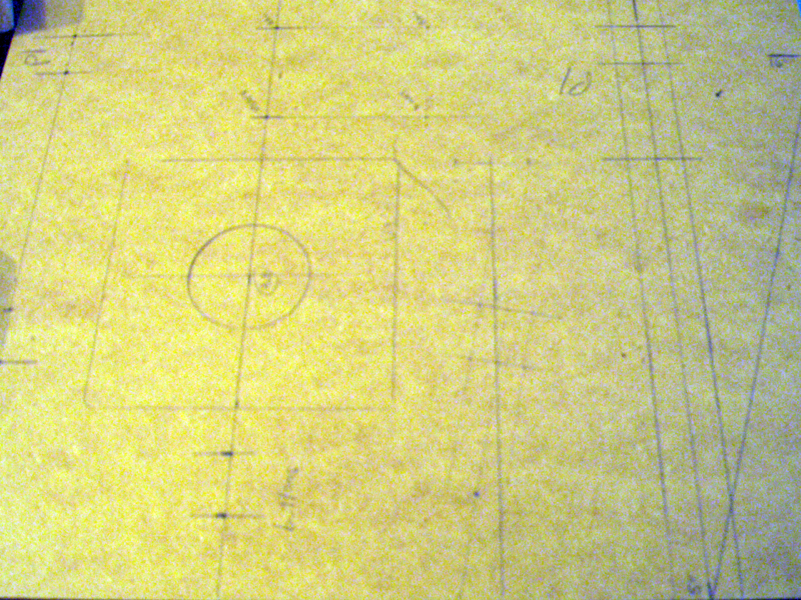
More pictures of the grid lines we used, it probably looks like a complex series of lines to anyone who wasn't involved in drawing it.
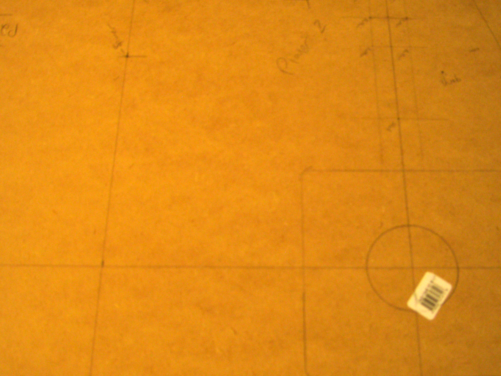

More examples of our layout.

The template was taped down to the melamine, which allowed me to drill every single joystick and button hole precisely. As you can see, there's not even 1/16" error on the holes.


A close up of player 1. The thumb button is offset 1 3/4". Originally I started with 1 1/2" like the rest of the buttons, but it left the thumb button too close to button 4. I played around with a few measurements but 1 3/4" ultimately seemed correct.


This is a close up of player 3. Player 3 and Player 4 are a 4 button configuration as that is the most number of buttons required.


This is a picture of me drilling what seemed like my millionth hole on the control panel. My Dewalt drill has a bubble on the back to ensure that my hole is going straight down. 1 1/8" spade bit was used for all the joystick and button holes.
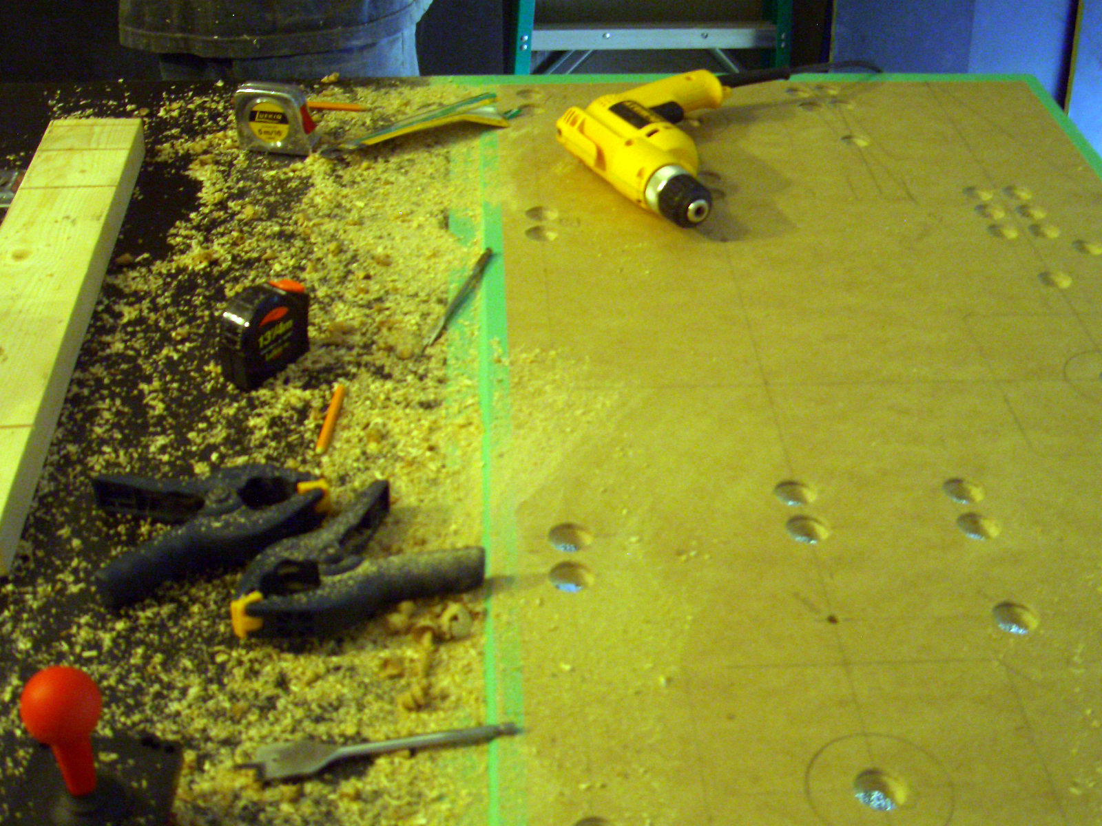

Drilling all the holes created an enormous amount of dust.
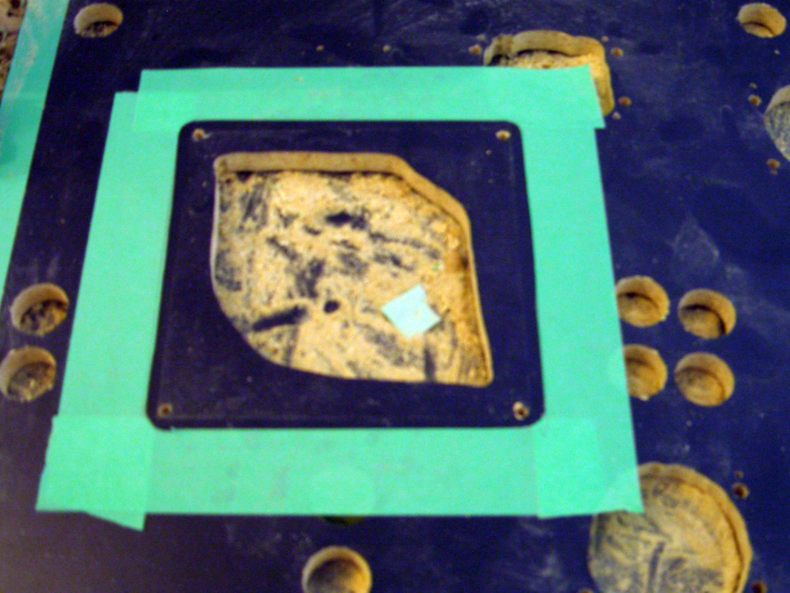
This is a side shot of the Player 3 trackball. J routed out the center, where the trackball needs to fit up and through to point to the flush plate.
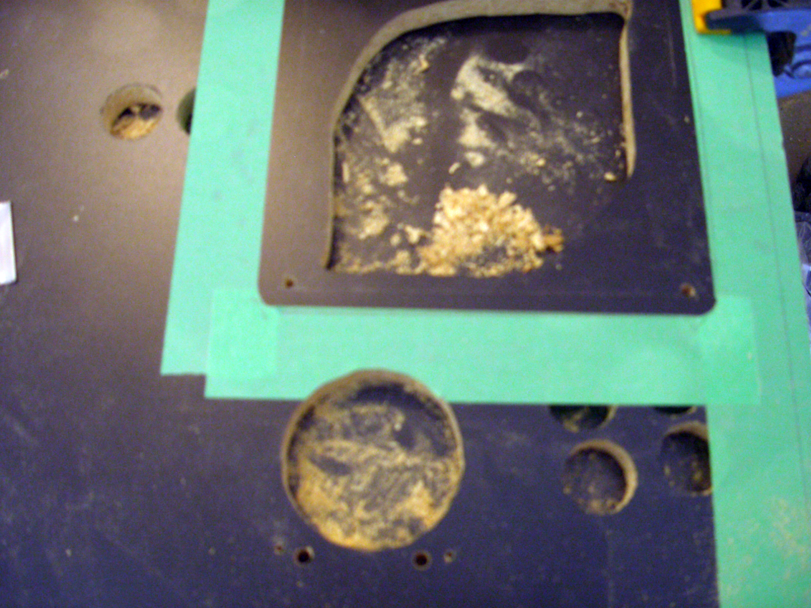
This is a correctly oriented shot of the player 2 trackball above the player 4 joystick.


This is a shot of the player 1 trackball, mounted to the left of the player 2 layout.
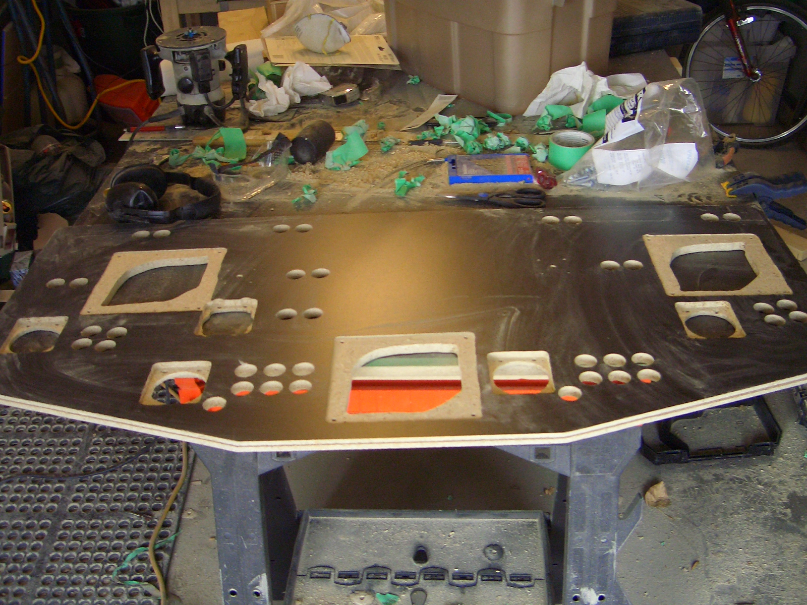
The end result. Everything is nicely lined up and symmetrical. Buttons are used for multiple controls wherever possible.
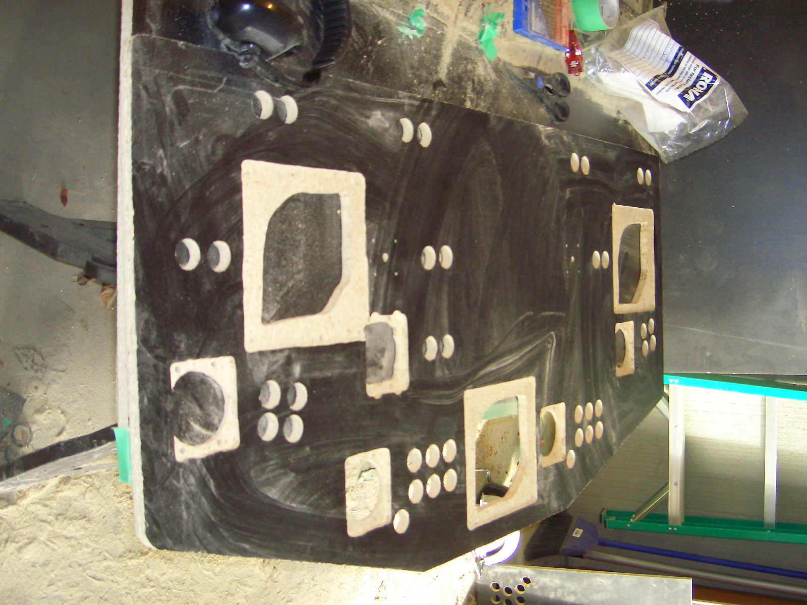
A nice perspective shot of the control panel.

A close up shot of J's fine routing skills. Each of the holes was taped, then traced around the required control, then a razor blade was used to cut the tape and provide a guide for the routing area.
Monday, October 8, 2007

Do you know the Tristan Rêveur quote about bad art? It's "bad art is more tragically beautiful than good art 'cause it documents human failure."

I'm currently working through the control panel layout. J was gracious enough to lend his time to do a mock up in AutoCAD. I did a test layout and it looks like we're going to have to rework some things.

My fan grills came in, after I decided to go with another company. I'll need to update my cost page to reflect the cost of the molex connectors for the power supply, the fan grills and the speaker covers.

I managed to mount the fan grills, as well as the speaker shelf. I think I'll need to mount the monitor to get a better sense of my control panel layout.

I won't be able to post pictures for a little bit, as I sold my camera. The intent was to replace my camera with the Nikon d40x. Unfortunately in that time span the project has left me a little cash deprived.
Updated the project status page.

Sunday, September 30, 2007

A thousand nations of the Persian empire descend upon you. Our arrows will blot out the sun!

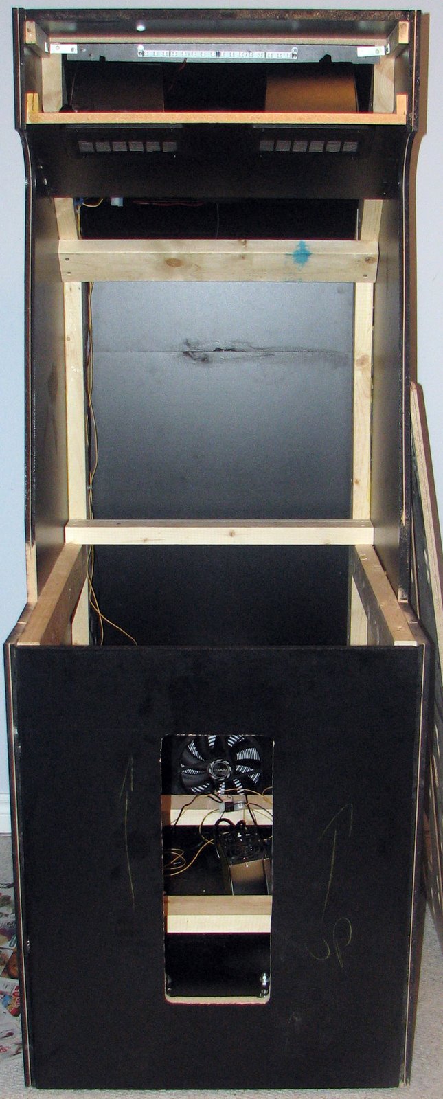
The cabinet is finally assembled. Well, almost.

The speaker shelf needs to be assembled, and the base piece and casters need to be attached. Other than that, you are looking at a project well along it's way to completion.

Slight accident when insuring all the pieces fit snugly in the cabinet. The angled back piece fell with a tremendous crash, damaging the edges. Some wood filler and enamel paint touched it up nicely.

This week I'll be concentrating on the control panel mock up. By next weekend I should be good for the remaining cabinet pieces to be attached, and to start construction on the control panel.


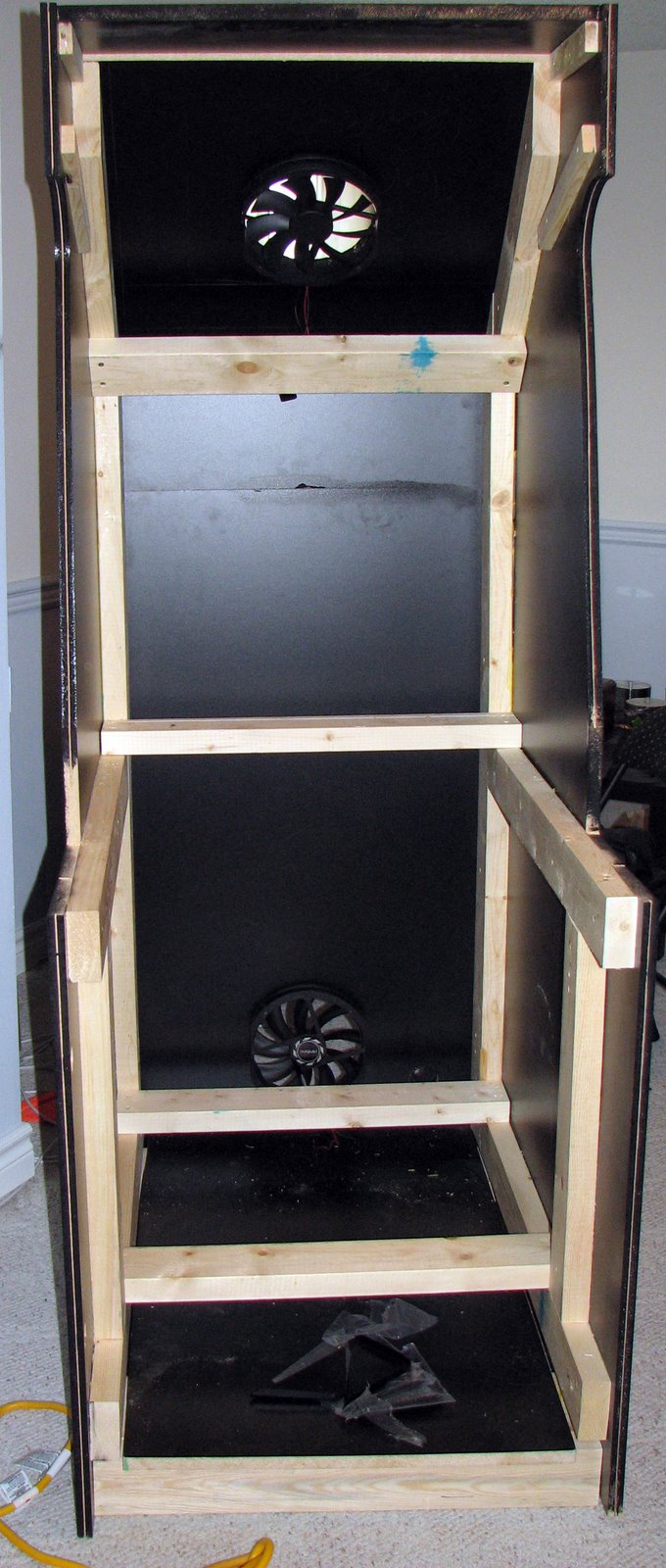
The blotching at the back is the enamel paint seeping through the crack at the back. You can see the wood frame on the inside that provides more stability and will ultimately support the monitor.


The pieces sitting on the bottom are the corner protectors. MDF has a bad habit of folding easily. The T-molding needs to be installed first though.

Full size shot.


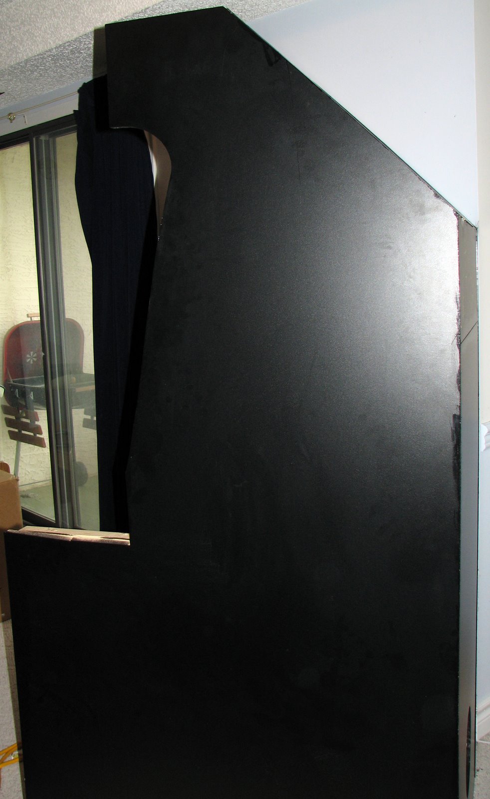
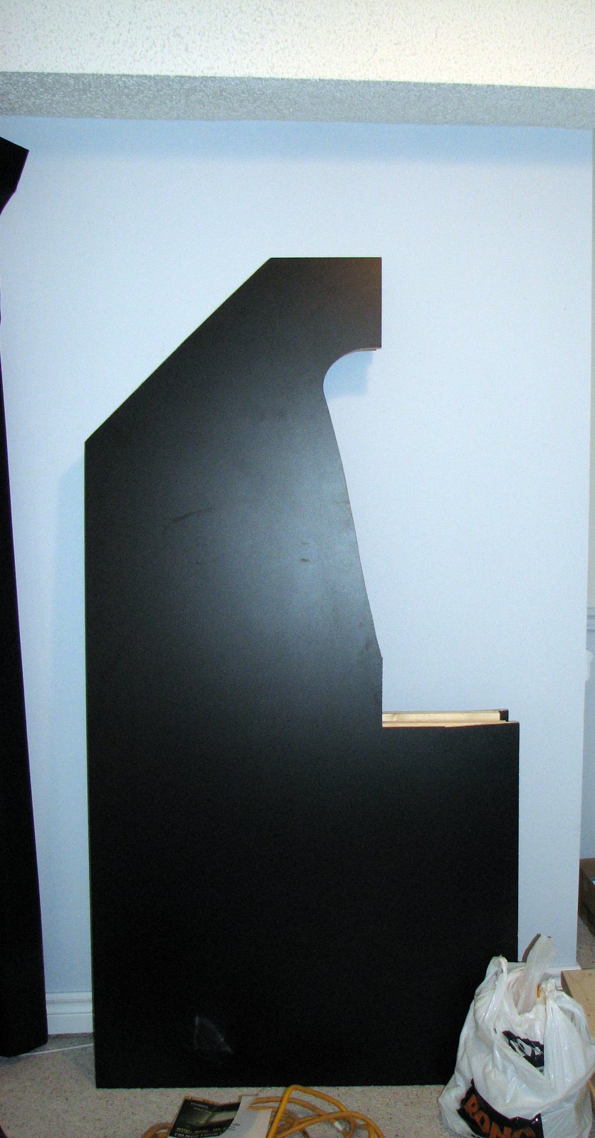
Side panel shot, nothing new here.

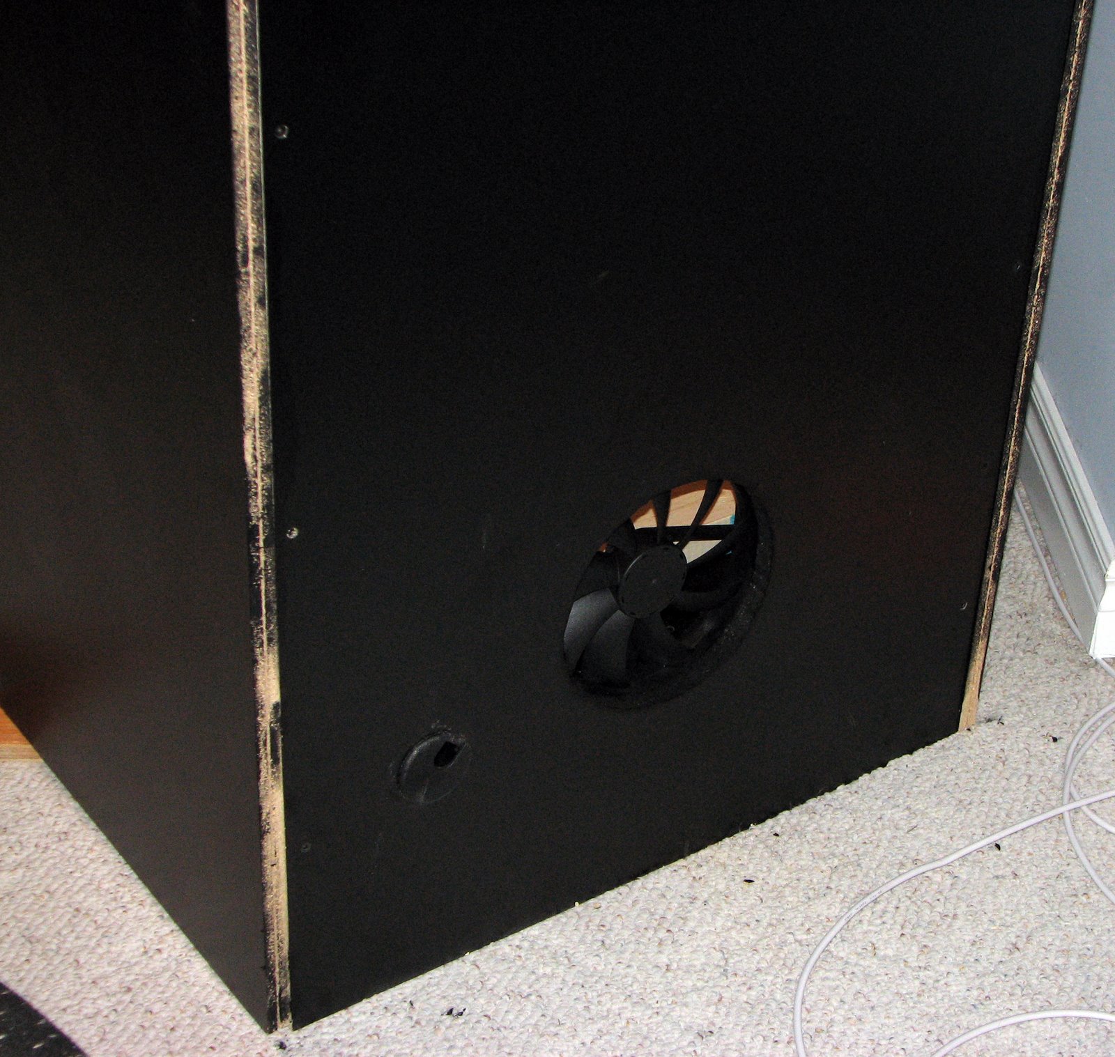
Lower back with the fan installed. The edging will be covered by T-molding.

Top back fan. It will look much better with the 254mm fan grill installed.


This is the lower fan, again will look much better with the 254mm grill installed.

Thursday, September 27, 2007

The tortoise lays on its back, its belly baking in the hot sun, beating its legs trying to turn itself over but it can't. Not without your help.

The cabinet cutting, routing and fabricating is complete. All the pieces were moved over to my house for assembly. We'll likely be putting this beast together on Sunday.

That will pave the way for me to start focusing on the control panel. With any luck the control panel will be a fraction of the work of the cabinet.

I completely underestimated the amount of hours and work that was involved in the cabinet construction.


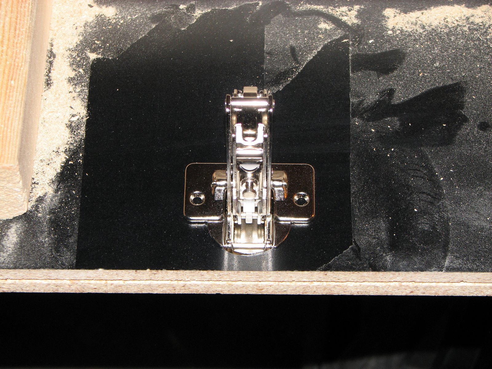
I didn't realize it at the time, but the European door hinges required a section to be routed out. The space had to be 1/2", keeping in mind we only had 3/4" of material to work with in the first place. To make matters more complicated, it was only 5mm from the edge, which we had already used a 3/32 bit on. To say I was concerned about punching through the side of the cabinet would be a big understatement.


J did a great job.


No wiggle room on the hinge at all, nice and snug.


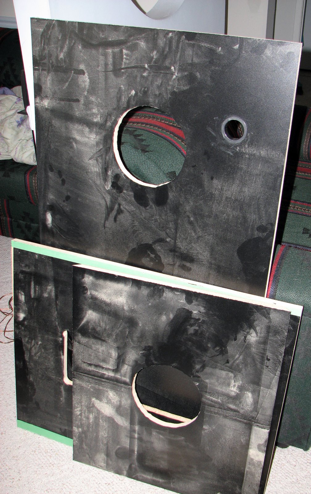
My house, now filled with pieces of arcade cabinet.


The back piece of the cabinet upside down, with the angled back piece and speaker shelf resting against it. You can see the amount of MDF dust all over it.


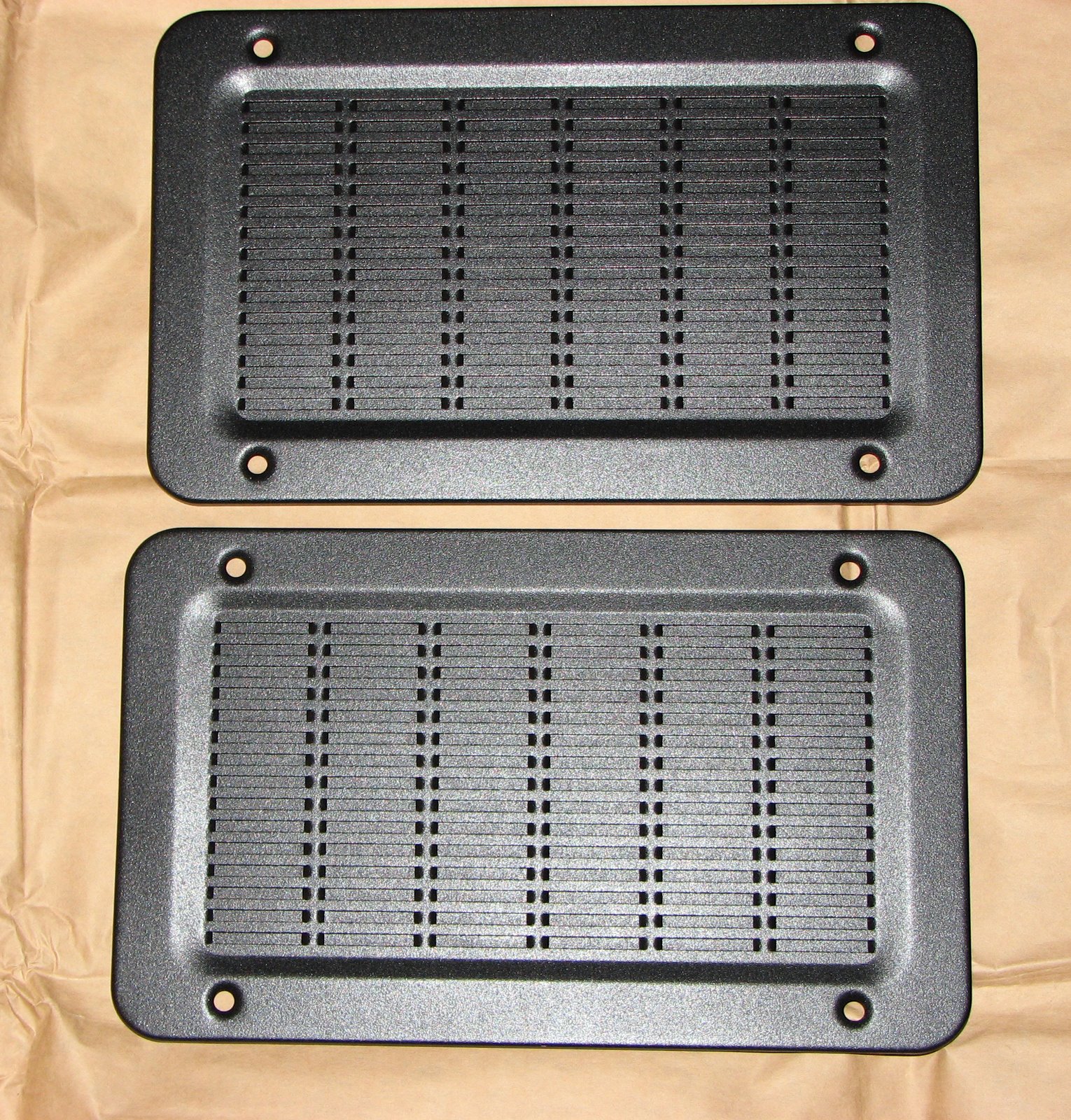
I had assumed the Midway speaker grills were plastic. They are, in fact, some sort of aluminum. The pictures don't do them justice, they look great.

Tuesday, September 25, 2007

You can help me. Whatever comes out of these gates, we've got a better chance of survival if we work together. Do you understand?

Another productive evening.

J and I managed to complete all the major cutting we need to do for the cabinet. There will be some minor frame support pieces tomorrow night, but they shouldn't be more than a few minutes.

The top, back, front door with coin door cutout, speaker shelf with cutout and all the fan cutouts are complete.

The coin door was the most difficult piece, it required some careful routing to ensure that the coin door fit properly. J touched it up a few times and now the coin door fits nicely.

Tomorrow we bring all the pieces to my place for assembly.

From there, my focus will be the control panel.


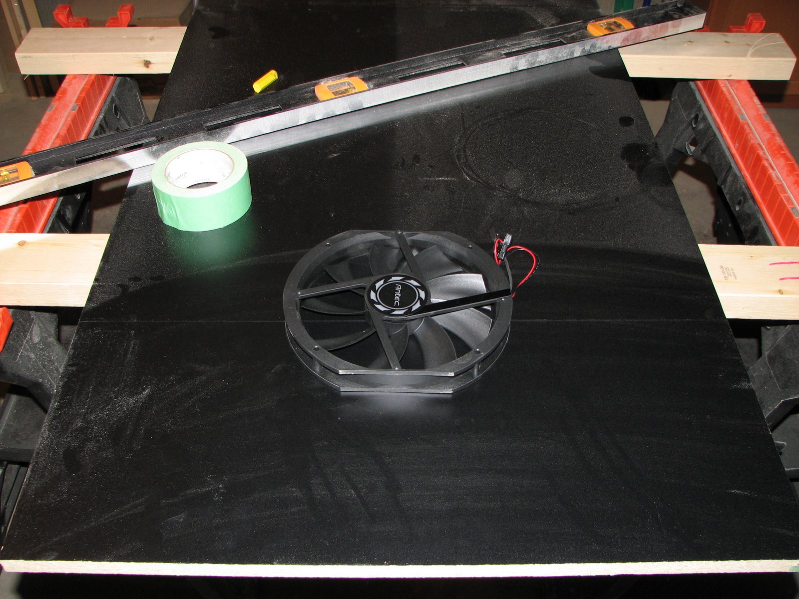
Using the 200mm DC fans to get a sense of size for the cutout.


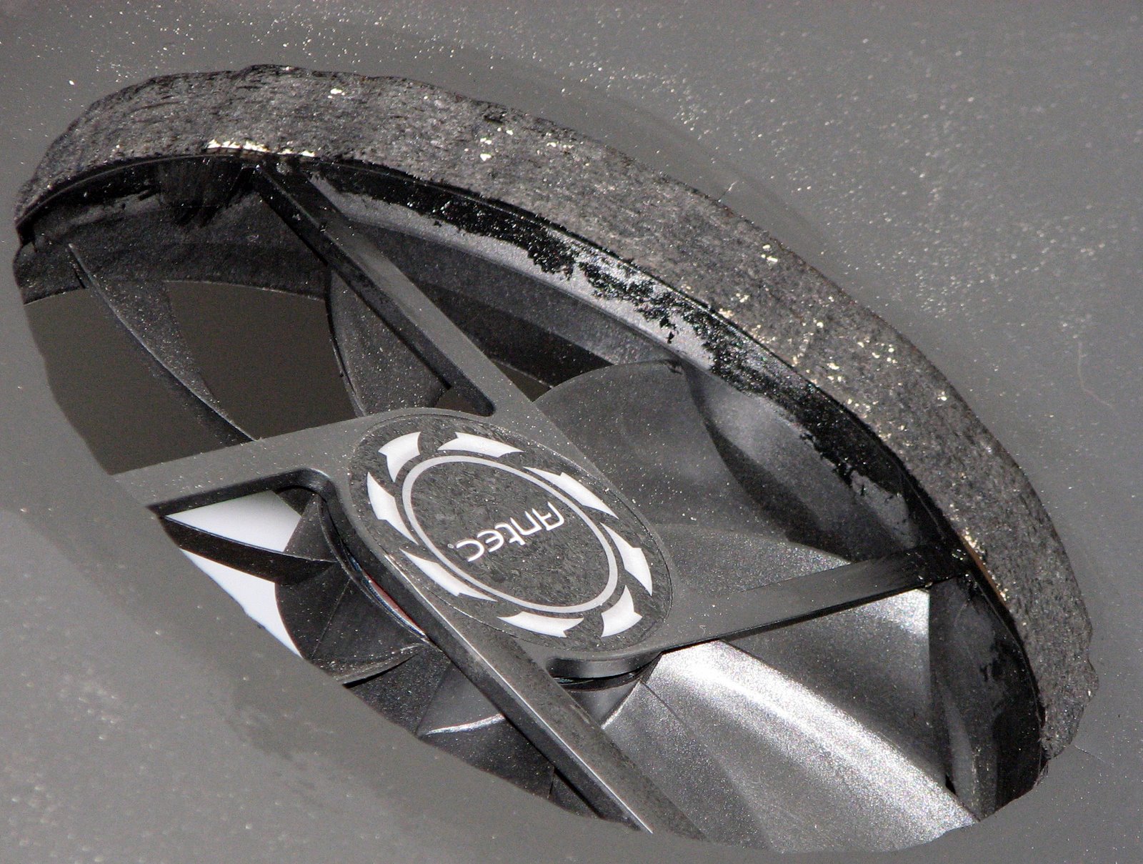
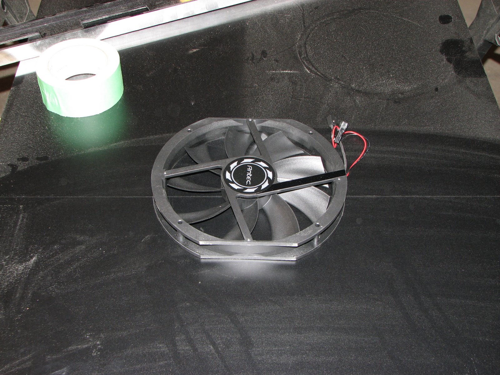
Close up picture of the Antec 200mm fan.


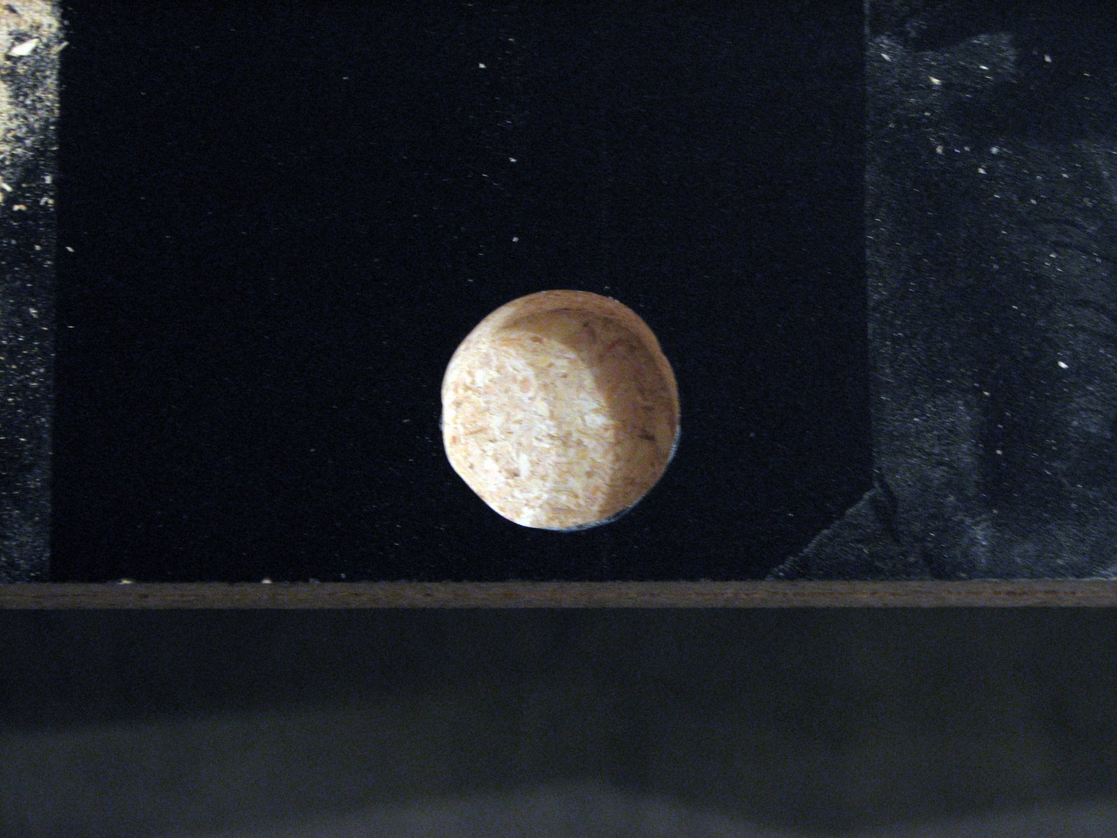
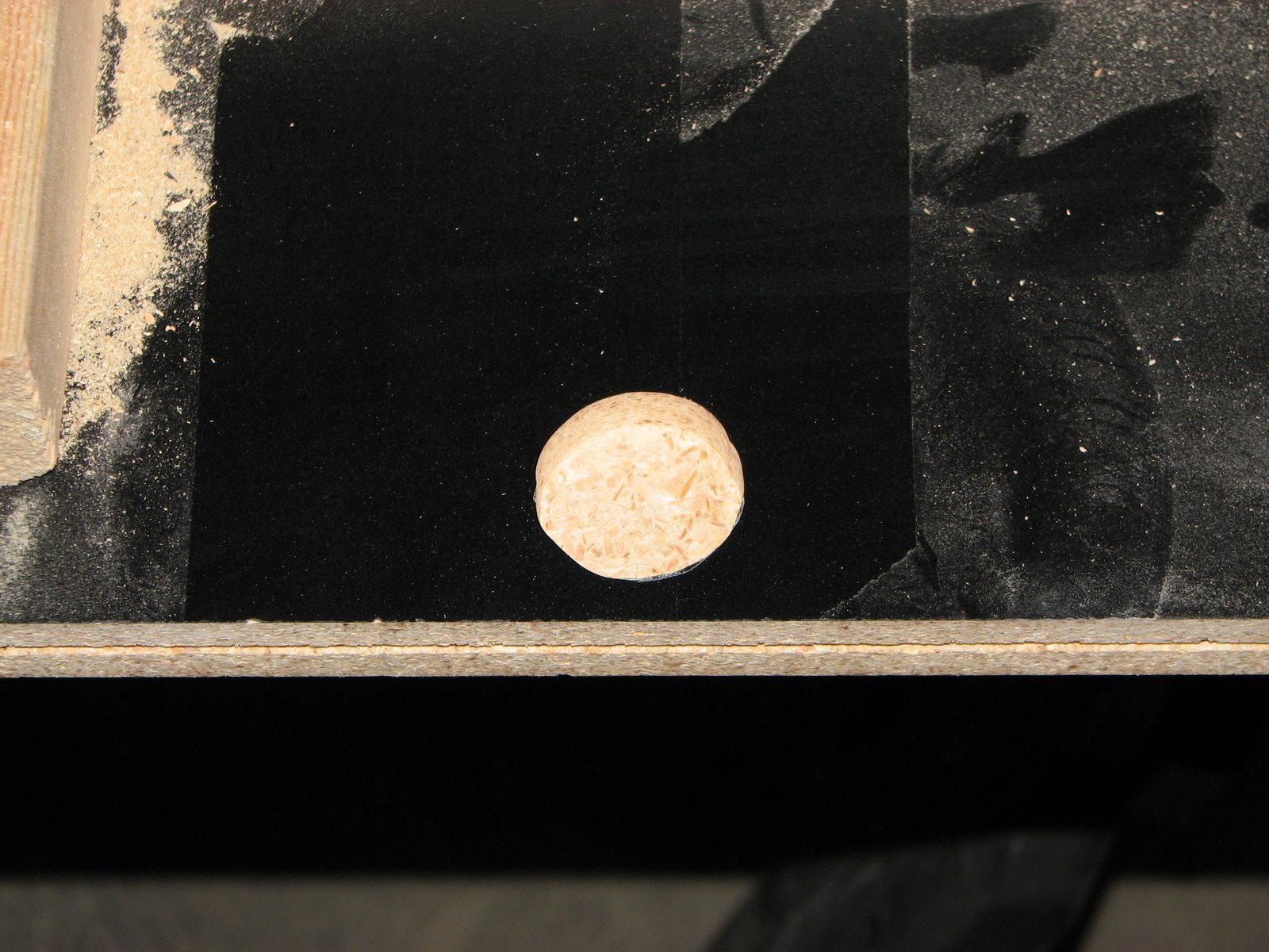
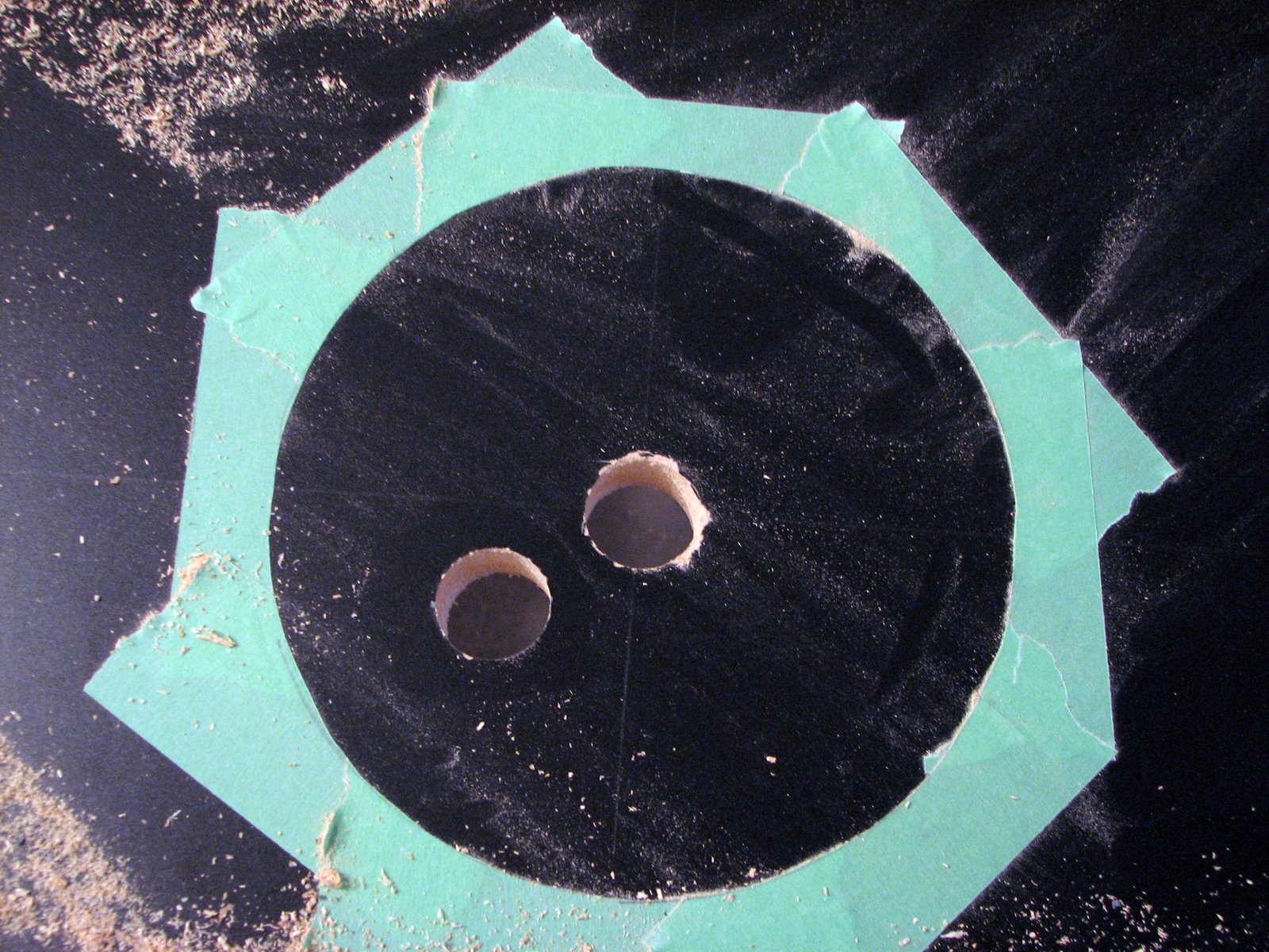
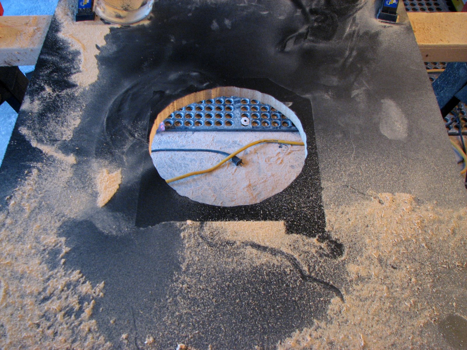
Used a 1 1/2" spade bit to cut a hole for the router to fit into. The spade bit made short work of the melamine.


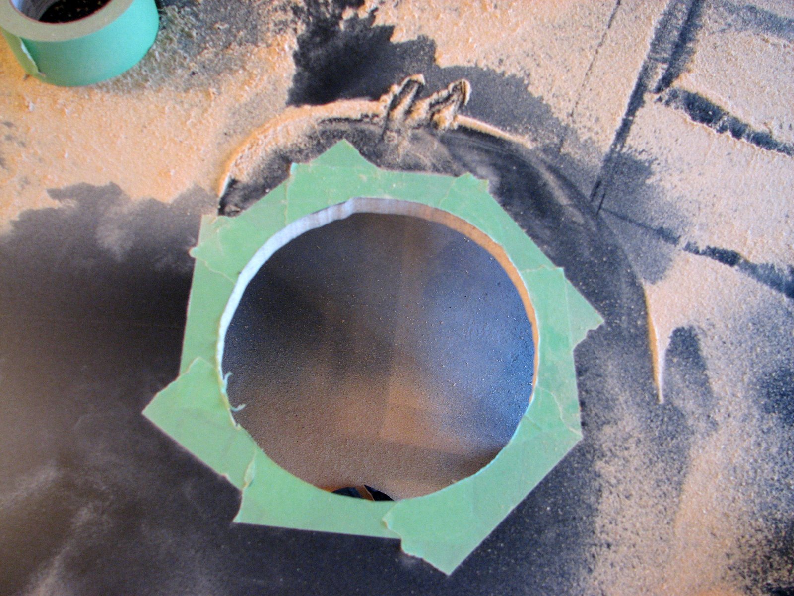
A few odd edges on the fan cutout, but it will be completely masked once the fan is mounted and the fan grills installed.


45 degree cut for the top back piece that sits at angle. Done with a circular saw, not a bad job.


Same technique as above used for the back panel. Another Antec 200mm fan will be installed to provide air intake from the back.


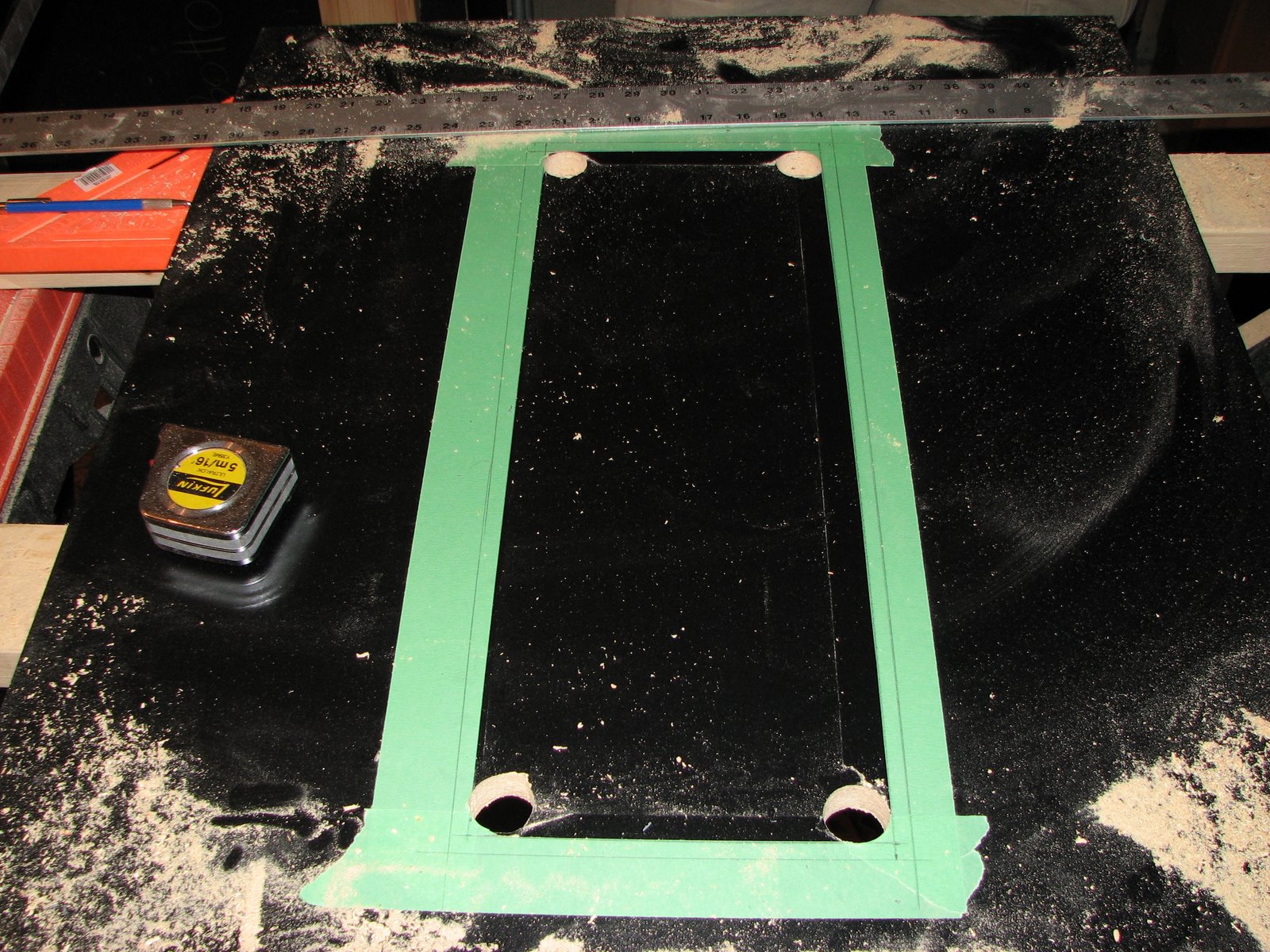
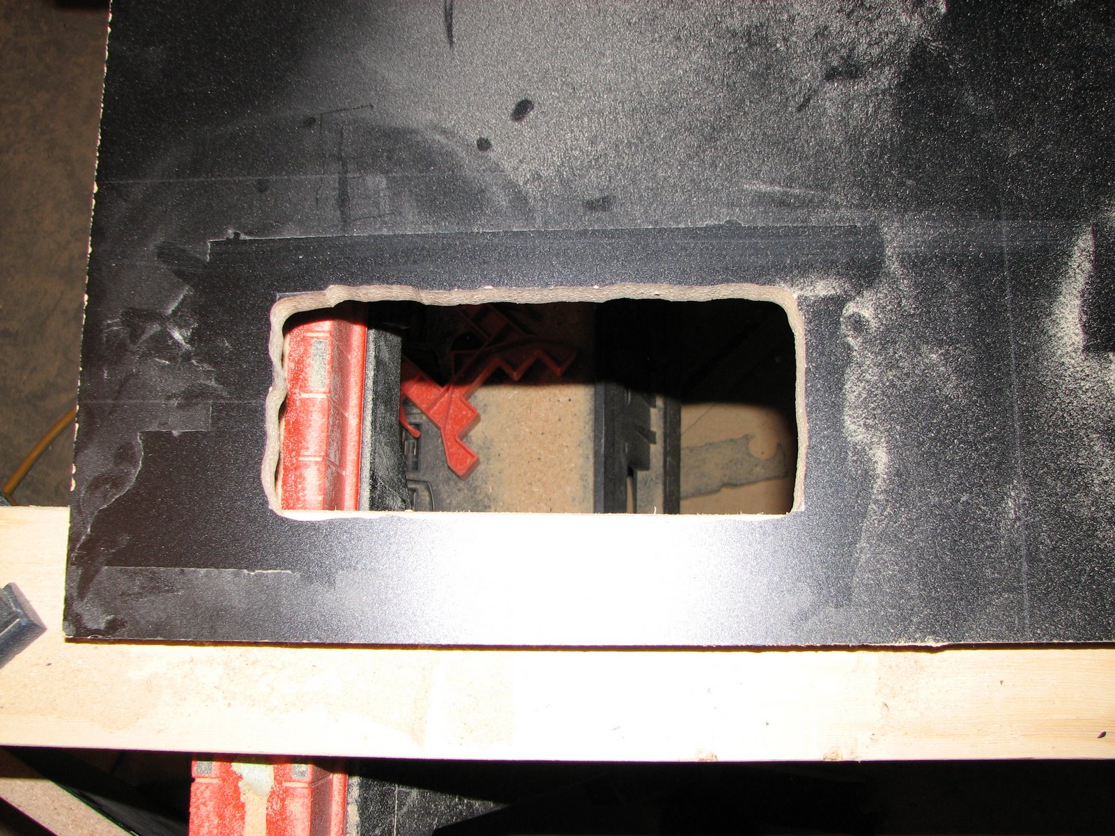
The layout for the coin door cutout. We were a little sloppy when we used the spade bit to cut the corners. We should have used the router to cut the corners, or more carefully measured. In the end it worked out fine because we had a 1/2" of play on either side of the coin door.


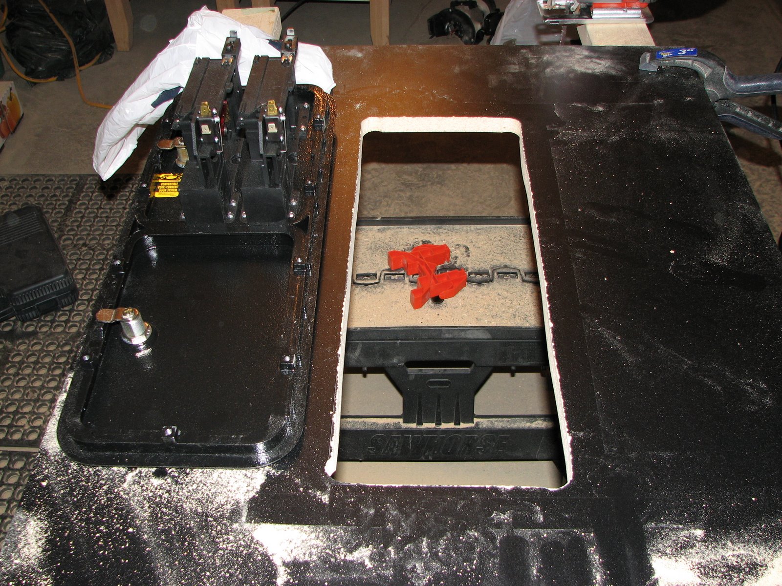
Cutout completed. As you can see, it's not exactly precise. Luckily the coin door hides any ugliness on the cut job.


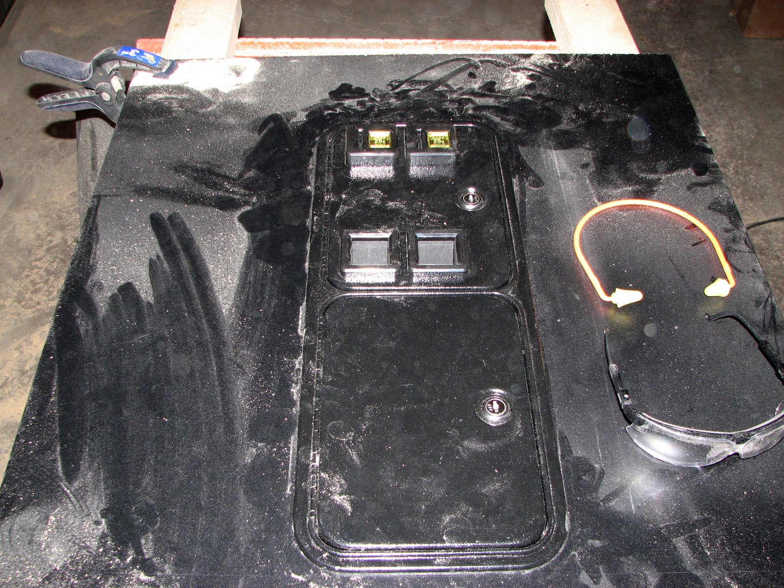
With the coin door installed, nice and snug. As you can see the router kicks up tons of MDF dust. Breathing protection is a must.


No traces of gaps around the outside edge. It really looks great.


Speaker cutout. The book wasn't exactly clear on the inside dimensions of the cutout. In the end we used the dimensions of the Klipsch 2.1 speakers and simply subtracted 1/2" from either side to cut the inside dimensions.


Not exactly a thing of beauty, any imperfections here will be covered by the speaker grills.